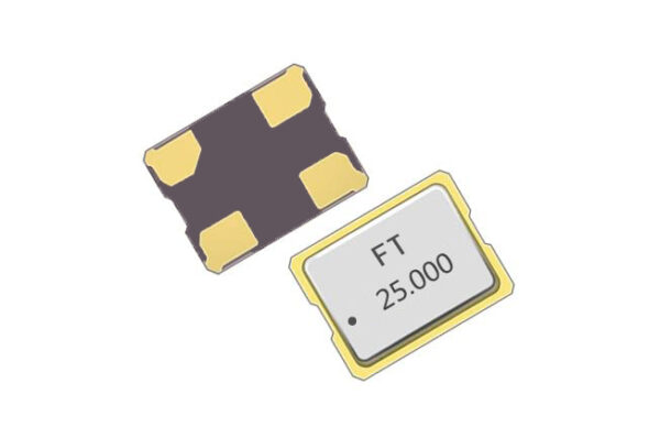
Understanding the Functions of Crystal Oscillator Pads
2026-02-28
The pins of a quartz crystal oscillator refer to the soldering points where the electronic component connects to the circuit, also known as "pin positions" or "pads". Quartz crystal oscillators are generally categorized into two types: passive crystal oscillators and active crystal oscillators, which differ in pin count and functions.
1. How to identify the direction of crystal oscillator pins?

Crystal oscillators fall into active and passive types, with different direction identification rules.Passive crystal oscillators are non-directional; reverse mounting will not damage the component.Active crystal oscillators are directional; reverse mounting may cause damage and requires careful identification.
Direction identification for passive crystal oscillators
Passive crystal oscillators (including 2‑pin, 4‑pin versions, etc.) are non-directional. Their pins have no positive or negative polarity, and reverse mounting causes no malfunction.
Direction identification for active crystal oscillators
Active crystal oscillators (e.g., 4‑pin packages) are directional. Confirm pin direction using these methods:
- Mark identification: Marks on the oscillator shell (such as a dot, notch, or printed mark) usually indicate Pin 1. Pins 2, 3, 4 follow counterclockwise from Pin 1.
- PCB pad features: Check the PCB layout; the chamfered or notched area corresponds to the empty pin or Pin 1.
- Typical pin functions: Common assignments are Pin 1 NC (Not Connected), Pin 2 GND (Ground), Pin 3 OUT (Signal Output), Pin 4 VCC (Power Supply). Exact definitions vary by model.
- Datasheet: The most reliable method is to check the datasheet of the specific model for pinout and functions.
2. How to repair a broken crystal oscillator pin?
The following fixes can be attempted, but success depends on the extent of damage.
- Inspect the pin: Use a magnifier or microscope to check if the pin is fully broken or only partially damaged. Gently straighten slightly bent but unbroken pins.
- Solder repair: For partial breaks or poor contacts:
- Remove old solder with a desoldering braid.
- Resolder carefully using thin solder and a soldering iron, ensuring a firm, short‑free connection.
- Control temperature and time to avoid heat damage to the internal crystal structure.
- Replace the oscillator: If the pin is completely broken or unrepairable, replace it with an identical model and solder properly.
- Prevention: Avoid excessive force during handling and limit soldering time to reduce mechanical and thermal stress.
How to correct frequency deviation
Celebrate the Spring Festival, ring in the New Year